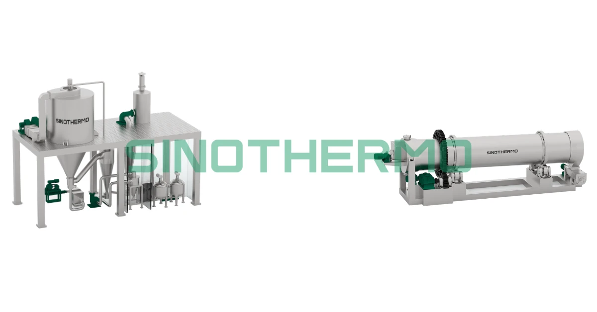
Lithium iron phosphate (LiFePO₄, LFP) cathode material is not produced in a single machine. It comes out of a five-stage chain — precipitation, precursor dehydration, slurry preparation and spray granulation, carbothermal calcination under inert atmosphere, and controlled cooling with deagglomeration — and the electrochemical quality of the finished cathode is largely decided in the two thermal stages, long before anyone measures a cell. This guide walks through what each stage actually has to achieve, which equipment fits, and where LFP lines most often go wrong.
If you are specifying equipment for an LFP plant, the important thing to understand early is that drying and calcination are not utility steps here. In many powder industries the dryer is the last thing chosen and the cheapest thing to change. In LFP, the dryer sets particle architecture and the calciner sets crystal structure and carbon coating. Get either wrong and no downstream process step can recover it.
Quick context: why the LFP process window is narrow
LFP has become the volume chemistry for energy storage and entry-tier EV packs because it is cobalt-free, thermally stable, and cycle-durable. Those advantages come from the olivine crystal structure — and that structure also brings the process constraint: LiFePO₄ has intrinsically low electronic conductivity and slow lithium-ion diffusion.
Manufacturers compensate in two ways, both of which are process-controlled rather than formulation-controlled:
- 1.Small primary particles with short diffusion paths, assembled into larger, well-formed spherical secondary particles so the powder still flows, packs, and coats.
- 2.A thin, continuous conductive carbon coating on the particle surface, formed in situ during calcination.
Both of those outcomes are produced by the drying and calcination equipment. That is why an LFP line is much less forgiving than a general chemical drying line, and why "a dryer that hits the moisture spec" is nowhere near a sufficient specification.
The 5-stage LFP production chain
Stage 1 — Iron phosphate precursor synthesis
Iron phosphate dihydrate (FePO₄·2H₂O) is produced by precipitation from an iron source and a phosphate source under controlled pH, temperature, and addition rate. The precipitation conditions set primary crystallite size, morphology, and impurity content. Everything that follows either preserves or degrades what precipitation created — no downstream stage improves it.
The precipitate is then filtered and washed. Washing efficiency matters more here than in most precipitation processes, because residual soluble salts carry straight through the thermal stages into the finished cathode.
Stage 2 — Precursor dehydration (crystal-water removal)
The washed filter cake carries two very different kinds of water: free surface moisture from the filtration step, and crystal water bound in the FePO₄·2H₂O lattice. They come off at different temperatures and they behave differently.
Free moisture is a conventional evaporative drying duty. Crystal water is a lattice transformation — it comes off over a defined temperature window that should be established on your material by thermal analysis (TGA/DSC), not read from a paper. Drive it too hard and the particles sinter and grow, surface area collapses, and the subsequent solid-state reaction with the lithium source becomes incomplete and uneven. That defect is invisible in the dried powder and permanent in the finished cathode.
This is the single most misunderstood step in the chain: precursor dehydration is a precision thermal step, not a bulk moisture-removal step.
Stage 3 — Slurry preparation and spray granulation
The dehydrated iron phosphate is milled and combined with:
- a lithium source — typically lithium carbonate or lithium hydroxide (drying behaviour of those salts is covered in our lithium carbonate and hydroxide drying guide);
- a carbon source — an organic compound such as glucose, sucrose, starch, PVA, or citric acid, which later pyrolyses into the conductive coating;
- water or solvent, plus dispersant, to form a millable, pumpable slurry.
The slurry is wet-milled to target primary particle size, then spray dried and granulated into spherical secondary particles. This is the stage where particle architecture is created: sphericity, secondary particle size distribution, internal density, and — critically — how intimately the lithium source, iron phosphate, and carbon source are mixed inside each granule before they ever see calcination temperature.
Spray granulation is doing two jobs at once: removing water, and assembling a composite particle. Sizing the dryer on evaporation duty alone addresses only the first. See how spray drying works for the underlying mechanism, and our spray processing in lithium battery materials article for the particle-quality science in more depth.
Stage 4 — Carbothermal calcination under inert atmosphere
The granulated precursor is calcined under nitrogen or argon. Three things happen simultaneously in the kiln, and they are often described as one step when they are really three:
- Carbothermal reduction. Iron in the precursor is in the Fe(III) state; in LiFePO₄ it must be Fe(II). The carbon source acts as the reducing agent, consuming part of itself in the process. This is why the atmosphere must be oxygen-free — oxygen competes for the carbon and sabotages the reduction.
- Solid-state reaction and crystallisation. The lithium source and iron phosphate react to form the olivine LiFePO₄ phase. Incomplete or uneven reaction leaves unreacted precursor or secondary phases such as iron phosphides or Fe₂P if conditions drift.
- Carbon coating formation. The remaining organic carbon pyrolyses into an amorphous conductive layer on the particle surface. Coating continuity — not just total carbon content — is what determines conductivity.
Commonly cited industry design targets place the calcination plateau somewhere in the region of 600–800 °C with an extended soak; treat that as an orientation figure only and confirm the plateau, ramp rate, and soak time against your own material. Too low and the reaction is incomplete; too high and primary particles grow, or unwanted phases appear. Both are one-way failures.
For the atmosphere requirement in detail — oxygen targets, closed-loop gas circuits, seals, and interlocks — see our inert-gas drying guide for battery materials.
Stage 5 — Controlled cooling, deagglomeration, and handling
The calcined product must be cooled while still under inert protection. Cooling a hot, freshly carbon-coated powder into ambient air re-oxidises the surface and can partially undo the coating you just spent a kiln cycle creating.
After cooling, granules are deagglomerated or jet-milled to the target particle size distribution, then screened, de-ironed, and packed. Because LFP is hygroscopic enough to matter and its surface chemistry is sensitive, nitrogen blanketing usually continues through cooling, conveying, and packing rather than stopping at the kiln discharge.
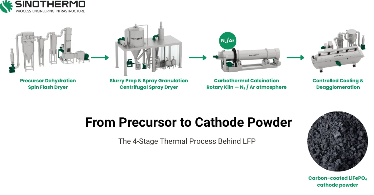
Equipment fit, stage by stage
| Stage | Process requirement | Equipment that typically fits |
|---|---|---|
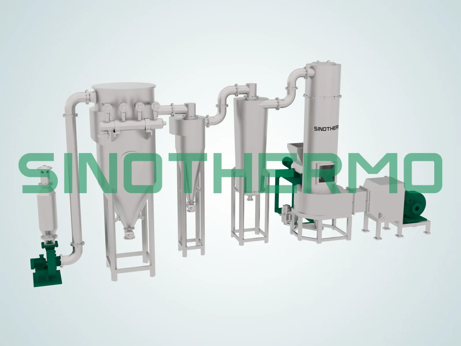
| Precursor dehydration | Controlled, moderate temperature; avoid sintering and surface-area loss; often handles a filter cake | Spin flash dryer or pneumatic (flash) dryer for continuous duty; vacuum paddle dryer, vacuum rake dryer or vacuum horizontal disc dryer where a gentler, low-temperature batch route is preferred |
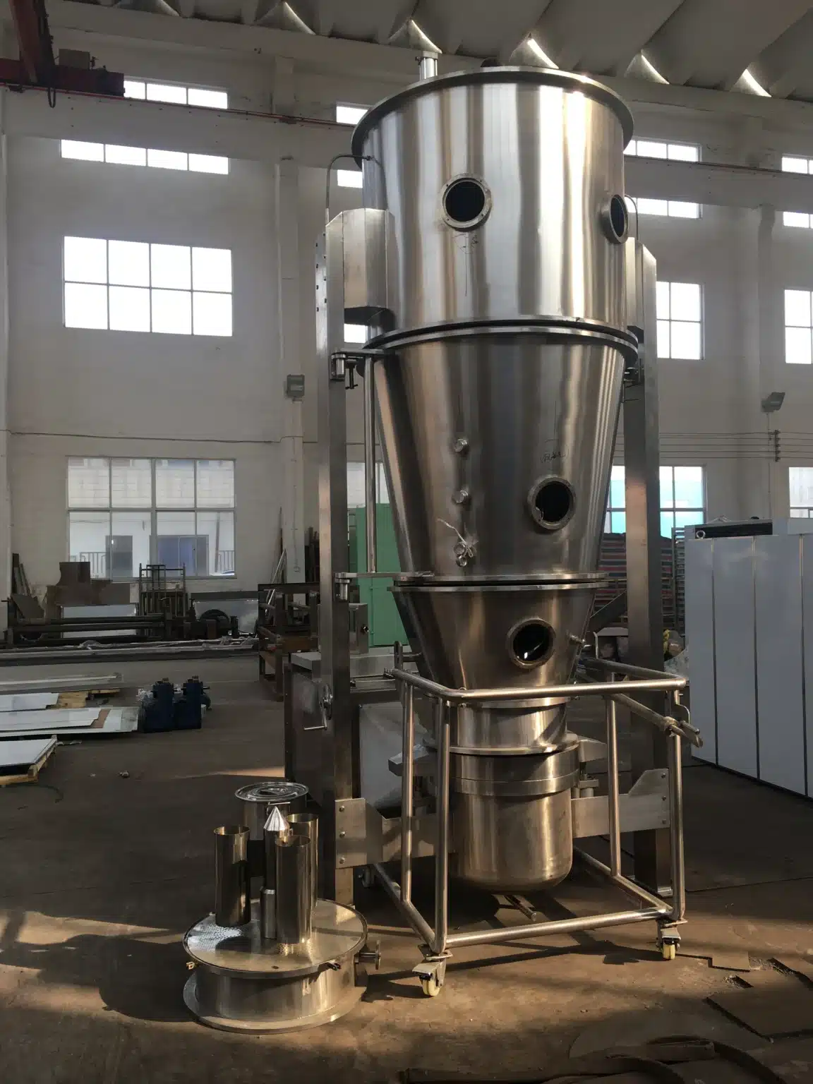
| Post-dehydration conditioning / cooling | Gentle, plug-flow residence with tight temperature control on a free-flowing powder | Horizontal vibrating fluidized bed dryer |
| Slurry → spherical granulate | Atomisation into uniform, dense, spherical secondary particles; abrasive slurry | Centrifugal spray dryer or pressure spray dryer, depending on target particle size and slurry rheology |
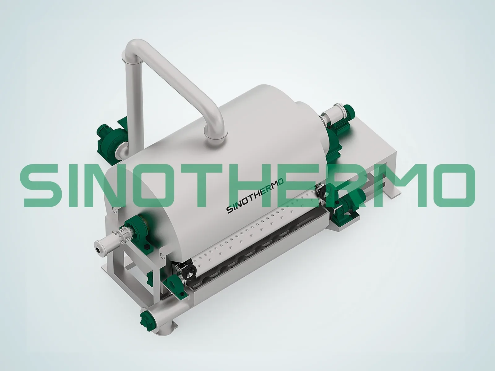
| Carbothermal calcination | High temperature, inert atmosphere (N₂/Ar), long controlled residence, tight temperature profile | Rotary kiln with inert-gas sealing and a multi-zone temperature profile |
For the wider equipment map across cathode, anode, and recycling routes, see our battery material drying solutions. If you are still at the stage of narrowing the dryer family, how to choose an industrial dryer covers the general selection logic.
Equipment referenced above: spin flash dryer, pneumatic dryer, vacuum paddle dryer, vacuum rake dryer, vacuum horizontal disc dryer, horizontal vibrating fluidized bed dryer, centrifugal spray dryer, pressure spray dryer, and rotary kiln.
Choosing the granulation route: centrifugal disc or pressure nozzle
Both atomiser types produce spherical granules; they get there differently, and the difference matters more for LFP than for a food or ceramic powder.
| Centrifugal (rotary disc) atomiser | Pressure nozzle atomiser | |
|---|---|---|
| Droplet formation | High-speed rotating disc; droplet size set mainly by wheel speed | High-pressure pump through a fine orifice; droplet size set by pressure and orifice |
| Typical particle size range | Finer to mid-range, generally narrower distribution at a given setting | Coarser, often preferred where larger secondary particles are wanted |
| Chamber geometry | Wide, shorter chamber (radial spray) | Tall, narrower tower (axial spray) |
| Sensitivity to slurry viscosity | More tolerant of higher viscosity and higher solids | Less tolerant; high solids raises pump pressure and wear |
| Abrasion exposure | Wheel and chamber wall wear | Orifice wear changes droplet size as it progresses |
| Turndown / adjustability | Adjust wheel speed on the fly | Adjust pressure or change nozzle set |
Iron phosphate slurry is abrasive. Whichever route you choose, wear is a process-quality issue, not only a maintenance issue: a worn nozzle orifice silently shifts particle size distribution over a campaign, and wear debris is metallic contamination in a material where metallic contamination is a cell-safety defect. Wear-resistant or ceramic-lined contact parts, and magnetic separation downstream, belong in the specification from the start. Our spray dryer machine guide covers the mechanical trade-offs in more detail.
Failure modes worth knowing before you buy
Hollow or "donut" granules. If the droplet surface forms a crust before the interior has released its water, the trapped vapour blows the particle open. The result is low tap density, fragile granules that break during conveying, and a broad, bimodal particle size distribution after calcination. The fix lives in inlet/outlet temperature profile, solids content, and atomisation — not in a later screening step.
Segregation inside the granule. Spray granulation is supposed to lock lithium source, iron phosphate, and carbon source together at fine scale. If the slurry is poorly dispersed or settles in the feed line, each granule enters the kiln with the wrong local stoichiometry. The kiln cannot mix; it can only react what is already adjacent.
Surface-area collapse at dehydration. Covered above — the defect that is invisible until cell testing.
Uneven bed depth or poor mixing in the kiln. Carbothermal reduction consumes carbon and generates gas. A stagnant or over-deep bed means the material at the bottom sees a different local atmosphere than the material at the surface, producing phase inhomogeneity across a single batch. Bed depth, fill ratio, rotation, and internals all belong in the calciner specification. Our rotary drum dryer guide explains the residence-time and flight-design principles that carry over to kiln design.
Re-oxidation at discharge. The kiln atmosphere can be perfect and still be undone in the thirty seconds after the material leaves it.
Metallic contamination. Fe, Cr, and Ni particles from worn contact parts can cause micro-shorts in a finished cell. In LFP this is an acute concern precisely because the product is itself an iron compound — you cannot simply screen for "iron" and be done. Contact-part materials, liner selection, and a de-ironing train are process-critical, not housekeeping.
Quality outcomes that trace back to drying and calcination
- Particle size and morphology — set at spray granulation, refined at deagglomeration; drives coating quality, electrode density, and rate performance.
- Tap density and compaction density — governed by granule sphericity and internal density, which is a spray-drying outcome.
- Carbon content and coating continuity — set by carbon-source selection and the calcination temperature/atmosphere profile. Total carbon is measurable; continuity is what actually determines conductivity, and it is a process-control result.
- Phase purity — uneven temperature or drifting atmosphere leaves unreacted precursor or secondary phases.
- Specific surface area (BET) — largely inherited from the dehydration step and then modified by calcination; too low and the reaction is sluggish, too high and processability and side reactions suffer.
- Residual moisture and metallic impurities — the two acceptance specs most likely to reject a shipment at the cell plant.
Common mistakes to avoid
- Treating precursor dehydration as a bulk moisture-removal duty. Specifying a dryer purely on evaporation rate and outlet moisture ignores the fact that this step also sets surface area. A machine that hits the moisture spec while overheating the material has failed at the thing that mattered.
- Sizing the spray dryer on evaporation load alone. Chamber geometry, temperature profile, and atomisation set particle morphology. Two dryers with identical evaporation capacity can produce very different granules — and only one of them is sellable.
- Ignoring abrasion and metallic contamination in the material selection. Iron phosphate slurry wears atomisers, pumps, pipework, and chamber walls. That wear shows up as drifting particle size and as metallic foreign matter in a product where foreign matter is a safety defect.
- Assuming the kiln atmosphere is inert because nitrogen is connected. Without a defined oxygen measurement point, continuous monitoring, and an interlock, you have an intention rather than a control. Seals, feed and discharge valves, and the gas circuit determine whether the target is actually held.
- Stopping the inert protection at the kiln discharge. Cooling in ambient air re-oxidises the carbon-coated surface. The protective atmosphere has to extend through cooling, conveying, and packing.
- Copying another plant's parameters instead of running a trial. Dehydration window, safe temperature ceiling, slurry rheology, and calcination profile are properties of your specific precursor, carbon source, and lithium source combination. Published figures are orientation, not a specification.
Prove the process window on your own material first
The numbers that decide whether an LFP line performs cannot be read off a table: the temperature window in which your precursor releases its crystal water without sintering, the slurry solids and atomisation settings that produce dense rather than hollow granules, and the calcination profile that completes the reaction without growing primary particles.
That is why SINOTHERMO operates an in-house pilot laboratory — bring your iron phosphate precursor, your slurry formulation, or your granulated intermediate and trial it before you commit to a specification. We measure the drying curve, confirm the dehydration window, run spray granulation trials to check granule morphology and density, and evaluate behaviour at the cooling and handling stages where re-oxidation and attrition usually appear. Backed by 20+ years of experience in industrial drying and calcination and deep customisation capability, our engineers use that trial data to size the chamber, the atomiser, the kiln, and the gas circuit correctly the first time — rather than correcting them after commissioning. You can see what the testing lab covers, or talk to our engineers about a trial.
SINOTHERMO — Process Engineering Infrastructure. We solve the process problem, not just sell a machine.
Conclusion
LFP looks like a simple chemistry and behaves like a demanding process. The cathode's electrochemical performance is written into the powder during two thermal stages — a dehydration step that must remove crystal water without destroying surface area, and a carbothermal calcination that must complete the olivine structure and the carbon coating under a genuinely oxygen-free atmosphere. Everything between them, the spray granulation stage, decides the particle architecture that both of those depend on.
Specify all three together, against your own material, and the line is right the first time. Specify them from a generic datasheet and the failure surfaces where it costs the most — at cell testing, after every downstream cost has already been added.
Building or expanding an LFP precursor or cathode line, and unsure what your dehydration window or calcination profile should be? Send us a sample: our pilot lab confirms the process window on your actual material before you specify.
✉️ mark.gu@sinothermo.com · 📱 WhatsApp: +86 180 2197 2660 · 🌐 www.sinothermo.com
SINOTHERMO — Process Engineering Infrastructure.
FAQ
Why does iron phosphate precursor need careful temperature control during drying?
Because the crystal water in FePO₄·2H₂O has to be removed within a defined temperature window. Dehydrating too aggressively causes particle sintering and growth and a loss of surface area, which leaves the later solid-state reaction with the lithium source incomplete and uneven. The defect is invisible in the dried powder and permanent in the finished cathode, so this step is a precision thermal duty rather than a bulk moisture-removal duty.
Why is LFP calcination done under nitrogen or argon instead of air?
Because calcination is a carbothermal reduction: the carbon source has to reduce iron from the Fe(III) state in the precursor to the Fe(II) state in LiFePO₄, and then pyrolyse into a conductive coating on the particle surface. Oxygen competes for that carbon, burning it off before it can do either job, and also oxidises the iron. An inert nitrogen or argon atmosphere protects both the reduction reaction and the carbon coating.
What equipment is used to turn iron phosphate slurry into LFP cathode powder?
A spray dryer or spray granulator — centrifugal disc or pressure nozzle, depending on target particle size and slurry rheology — converts the slurry into uniform spherical secondary particles. A rotary kiln operating under an inert atmosphere then carries out the carbothermal calcination that forms the final crystalline, carbon-coated LiFePO₄. Precursor dehydration ahead of the slurry stage typically uses a flash dryer or a vacuum paddle, rake, or disc dryer.
Does LFP production require both drying and calcination equipment?
Yes. Precursor dehydration and spray granulation are drying-temperature operations that set moisture, surface area, and particle architecture. They are followed by a separate, much higher-temperature calcination step that completes the crystalline structure and the carbon coating. The two duties cannot be combined into one machine because their temperature ranges, atmospheres, and residence-time requirements are different.
What causes hollow or broken granules in spray-granulated LFP precursor?
Hollow or "donut" particles form when the droplet surface crusts over before the interior has released its water, so trapped vapour blows the particle open. The result is low tap density and fragile granules that break during conveying and calcination, giving a broad or bimodal particle size distribution. The cure is in slurry solids content, inlet and outlet temperature profile, and atomisation settings, not in downstream screening.
How is metallic contamination controlled in LFP precursor drying equipment?
Iron phosphate slurry is abrasive, so atomisers, pumps, pipework, and chamber walls wear during a campaign, and that wear debris is metallic foreign matter in a material where Fe, Cr, and Ni particles can cause micro-shorts in a finished cell. Control comes from wear-resistant or ceramic-lined contact parts, monitoring atomiser wear as a quality parameter rather than a maintenance one, and a de-ironing and magnetic separation train before packing.

Mark Gu
Passionate about enhancing customer experiences and streamlining operations, Mark focuses on building strong relationships, fostering innovation, and leading teams to achieve exceptional service and efficiency.
Email: mark.gu@sinothermo.com
Phone: +86 18021972660